A bit more back-to-basics thing this time, reseting and such. The
goal of this bit of notes 'n stuff is to show exactly how-to build
a very simple, bootable firmware image for x86 machines out there.

So, when a computer boots, cpu fetches BIOS from ROM memory,
runs the BIOS which will do all kinds of stuff and then loads bootloader
from disk & passes controll to the bootloader.

This is all cool 'n dandy, but how does it work in practise?
When the CPU is powered up, it gets the first instructions to execute
from address 0xFFFFFFF0, 16 bytes below 4Gb. These 16 bytes are
reserved for 'reset vector', a small piece of code, that allows BIOS
programmers to choose where to jump next in the ROM memory.

Apart from allowing programmers to choose the following actual
entrypoint of the motherboard firmware, it might also allow such
wizards as motherboard designers to alter the location where
ROM memory is wired to. Atleast I'd guess so, I'm not an
expert on motherboard design, but I don't see any reason why not.

Anyway, back to the original topic. We now know that we'll have to
have valid code at address 0xFFFFFFF0, as CPU will read first
instructions to execute from there.

The very first thing we want do in our code is to disable interrupts,
jump to our actual entrypoint, and then disable TLB.

- Interrupts must be disabled very early on, because we don't yet have
IDT/IVT to use, just like with bootloader and/or kernel developement.

- TLB must be disabled to ensure that, even though paging is disabled,
we don't get silly addresses / false addr translations from
memory management unit (MMU).

The bare-bones source code of ours could currently look
something like this:
; to assemble this: nasm -fbin -o firmware.bin firmware.asm
bits 	16
org 	0xfffe0000
times 	0x10000 db 0

entry16:
	xor 	eax, eax
	mov 	cr3, eax 	; disable TLB
	cli
	hlt
	jmp 	$ - 2

; fill rest of the image with FF bytes, leave 0x10 (16) bytes
; free for our reset vector.
times 	0x20000 - 0x10 - ($ - $$) db 0xff

__reset_vector:
	cli
	jmp 	entry16
So, the code above just disables interrupts, and then
jumps into infinite loop. You can test the code easily by running:

./qemu-system-x86_64 -bios firmware.bin -d in_asm

This command runs the qemu emulator using firmware.bin file as it's
bios, and outputs every executed instruction to stdout.
Now, the previous code should be pretty cross-platform, running on
many different motherboards. However, from here on things will get
interesting. As many if not all manufacturers like to toss in their
own superio & stuff, I'll be showing how-to do stuff with Qemu.

To continue following along with something other than Qemu emulator,
you should first take a look into libreboot & coreboot projects to
see if your motherboard is supported by them. If it is, you can
easily use those projects as reference on how-to implement stuff, if
not, then you'll have to rely on finding datasheets for your board
specific stuff.

The next thing to do would be initializing SuperIO. This would be
must-have with any real machine, but with Qemu it's extremely
simple, all we have to do is to write 2 null bytes to port 0x3f8.

Now we have SuperIO done, it's time for serial port init.
With Qemu, after initializing SuperIO you don't really _have_ to
initialize serial ports correctly, but I'll add this part here anyway,
it might hopefully be useful to someone who is doing this with a real
machine instead.

The registers to configure serial port go as follows,
assuming DLAB is 0:

	Base + 0 : Data register, aka rx/tx buffer
	Base + 1 : Interrupt enable
	Base + 2 : Interrupt identification and FIFO control
	Base + 3 : Line control
	Base + 4 : Modem control
	Base + 5 : Line status
	Base + 6 : Modem status
	Base + 7 : Scratch register

The above list differs slightly with DLAB set to 1:

	Base + 0 : Least significant byte for baud rate
	Base + 1 : Most significant byte -

We will only be printing hello world, and not receiving any
messages/input, so interrupts can be disabled.

The baudrate of uart controller is by default (afaik) 115200,
which is quite speedy for real hardware. We're going to set the
baudrate of 9600 instead, not use parity, use 8 bits, and 1 stop bit.
We're also going to enable FIFO. To make this more efficient, you
definitely should use interrupts and not just poll, but this is a
hello world bios so I wont bother with such now...

The code below is pretty much just copy of osdev serial port
init, with only baudrate changed, as I was too lazy to reinvent the
wheel with this one.
mov 	dx, 0x3F9 		; base + 1
xor 	al, al 			; disable interrupts
out 	dx, al

add 	dx, 2 			; base + 3
mov 	al, 0x80 		; enable DLAB
out 	dx, al

sub 	dx, 3 			; base
mov 	al, 12 			; 115200 / 12 = 9600, baudrate
out 	dx, al

inc 	dx 			; base + 1
xor 	al, al 			; high byte of divisor
out 	dx, al

add 	dx, 2 			; base + 3
mov 	al, 3 			; 8 bits, no parity, and 1 stop bit
out 	dx, al 			; and set DLAB = 0

dec 	dx 			; base + 2
mov 	al, 0xC7 		; enable and clear FIFO
out 	dx, al

add 	dx, 4 			; base + 4
mov 	al, 0x0B 		; IRQs enabled, even though I'll
out 	dx, al 			; ignore interrupts, but oh well..
				; Also RTS/DSR set
So, for this firmware thingy to work, all there is left to do now is
to actually print the hello world. We don't need stack & such for now,
nor are we implementing proper print yet, just a simple one for testing.

To print the characters out to Qemu serial port, all you gotta do is to
write them out to 0x3f8. This, once again, is slightly more complex task
with real hardware. Unlike with real machines, we don't have to worry
about any delays what so ever, and we can just blast the data out at
full speed. In real world serial conns, you should make sure you're
slow enough to everything to work, good luck :)

One little sidenote you should be vary of, that I didn't take into
account in very long time, and which is why my TinyBIOS thingy is still
having some silly design choices, is that even though CS is set to
0xF000, the ES and DS are not. This means that to use string operations,
you should set the ES and/or DS to point to ROM too, aka set their values
to F000 aswell. I was silly, left them to 0, and kept wondering why
on earth lodsb does not read the values I expect it to load, as I was
reading from 0x0000XXXX instead of 0xFFFFXXXX.

Anyway, back to business, let's implement a simple test print:
; print expects ds:si to point to null-terminated string to print.
test_print:
	mov 	dx, 0x3f8
.start:
	lodsb
	test 	al, al
	jz 	.done
	out 	dx, al
	jmp 	.start
.done:
	ret
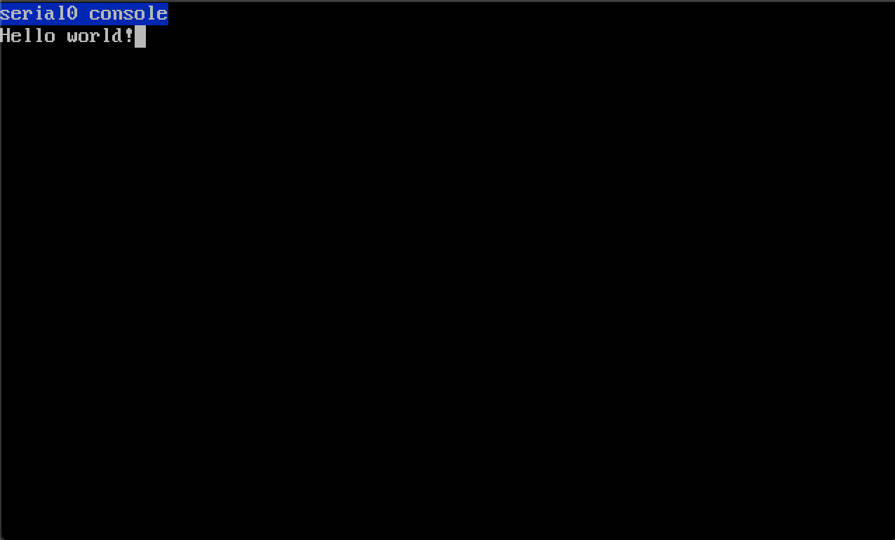
You're still here? amazing, congraz, you should now have all the
bits 'n pieces to build minimalistic firmware that prints hello world
on Qemu :)

If you happen to follow along and make the effort to build this all
to work on real bit of hardware, amazing ! I hope I have the motivation
to do the same eventually aswell.

Now, let's put it all together:
bits 	16
org 	0xfffe0000
align 	4
times 	0x10000 - ($ - $$) db 0

entry16:
	cld
	xor 	eax, eax
	mov 	cr3, eax

	mov 	dx, 0x3f8
	xor 	al, al
	out 	dx, al
	out 	dx, al

	mov 	ax, 0xf000
	mov 	ds, ax
	mov 	si, msg_ptr
	jmp 	test_print

msg_ptr:
	db "Hello world", 0

test_print:
	mov 	dx, 0x3f8
.start:
	lodsb
	test 	al, al
	jz 	.done
	out 	dx, al
	jmp 	.start
.done:
	cli
	hlt
	jmp 	$ - 2

times 	0x20000 - 0x10 - ($ - $$) db 0
__reset:
	cli
	jmp 	entry16 - ($ + 2)
	times 	12 db 0